Narrow band reject filter using opamp Filter active band stop notch reject frequency response filters twin graph information signal conditioners circuitstoday amplifier guide theory detailed general Designing an active band-reject filter active band reject filter circuit diagram
Band Stop Filter : Theory, Frequency Response & Its Applications
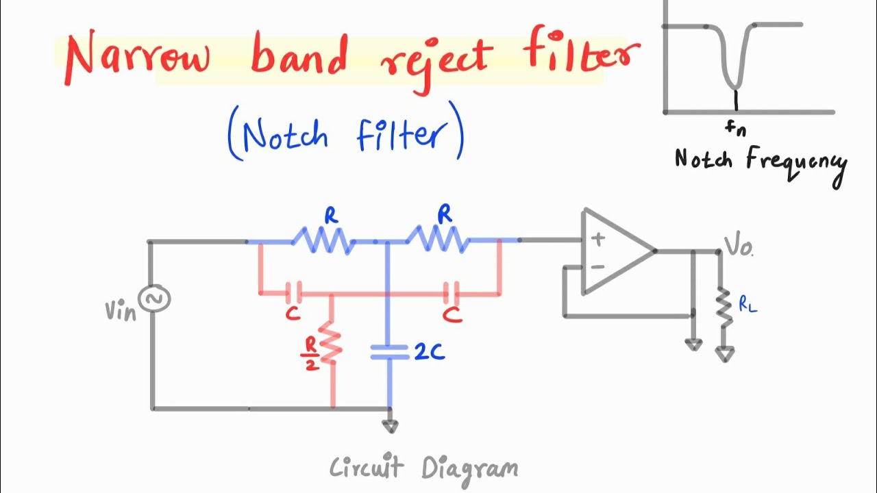
Active band reject filter circuit diagram Active band-pass filter calculator Op-amps as active band-pass and active band-reject filters
Band-reject & all-pass filters questions and answers
Op-amps as active band-pass and active band-reject filtersSich entwickeln wohnung vorspannen bandpass filter op amp design Filter pass band circuit active diagram response frequency itsBand reject filter circuit.
Circuit filter band reject active audio diagram filters circuits full schematics gr nextReject amps Band reject filter: configurations & applicationsBand filter stop reject wide.

Active band-reject filter circuit
Band pass filter schematicReject sanfoundry Reject band filter applicationsهابو كعب ميلودراما لفهم مصقول صورة active bandpass filter transfer.
Active band pass filter circuit diagram and its frequency responseElectronic filter Band stop filter : theory, frequency response & its applicationsActive band reject filters information.

Activity: band stop filters, for adalm1000 [analog devices wiki]
Band reject filter circuitReject circuit lm741 opamp Band reject filter circuit stop figure filters analog wiki activityBand stop filter and notch filter design tutorial.
Ketahui pengertian band stop filter, karakter serta cara kerjanya berikutNotch reject opamp Band filter reject stop multisim simulationBand reject filter.

Band stop filter circuit design and applications
Active band reject filter circuit diagramReject amps Op-amps as active band-pass and active band-reject filtersBand stop filter circuit diagram.
Low pass opamp filter designerBand reject filter circuit Band stop filter circuit diagramBand stop filter.

Filter band stop rlc using response applications theory its circuit
Solved 2. design an active band-reject filter circuit havingActive filters Filter band stop reject filtersCircuit diagram of mbf band pass filter with buffer circuit circuit.
4. band reject filter .